Questions about CNC and programming
What is an Integer variable?
Integers are a type of variables that hold a whole number, and it can not have a fractional part. For example 21 is a whole number and can be stored in an integer. Integer are really reference to memory location that is designated to hold a whole number variables. Integers include two groups these are signed and Unsigned. Unsigned hold bigger numbers (to the power of 2 bigger) but this type can only hold positive numbers. Signed can hold positive and negative values.
What is a floating point variable?
Often we need to use a number that can hold fractional numbers such as 21.35 or 0.2, a variable that can hold this type of value is called a “floating point”. A floating point variable is typically 32 bits, there are also 64 bit double floating point, these offer more precision, but in most industrial applications these are not needed. Floating point numbers are complex they have a fraction (23 bits) a exponent (like in logs) and bit 31 is the sign bit. Floating point is accurate over around 10 digits after which a float is an approximation and a double should be used.
What is a string?
Printable characters are normally stored in “strings”. A string is a collection (called an array) of bytes stored at consecutive memory locations. A string can hold any digital data!
What is a pointer?
Pointers are variables that are used to point to a block of memory. These are the most difficult variables to understand. However think of these as a book mark, it is like saying “page 99” for example. Pointers are used to give the start of a memory location. Pointers should always unsigned integers. Pointers can point to any of the data types, however a pointer to a floating point is still a unsigned integer.
What is CNC?
CNC means Computer Numerical Control, literally is means that a computer is controlling a machine and that computer can follow instructions that are written in a binary or text form. Many CNC machines actually mean that they can be programmed using a text file with a code called "G code". G Code uses a series of instructions that start with a G such as G0 for rapid move. For example G0 X100 Y50 Z10 means rapid mode to position 100 in the X dimension, 50 in the Y dimension and 10 in the Z.
What is G Code CNC?
G code is a system where movements of a machine are listed in a text file. Normally G Code is written from a post processor or using a text editor. This enables computer aided design systems to produce a cutting list, where all the machining is defined by G code commands.
Most G code command start with a G (which can be upper or lower case), the character G is followed by a number like 0. The vast majority of commands that cause motion begin with a G. There are other commands that begin with other characters such as F, S and M.
- G codes cause motion or alter motion parameters. Example G1 X10 Y5 Z-1
- M codes are for miscellaneous are used to control non motion issues such as turning coolant on etc. Example M5 stop spindle
- F is for feed rate. This sets the speed of the feed moves example F1200 (set the speed to 1200 per minute)
- S controls the spindle. The S command can change spindle modes like the speed, direction and on or off.
- X designates a position for the X axis.
- Y designates a position for the Y axis.
- Z designates a position for the Z axis.
- P dwell or number of turns parameter.
- R normally used for radius.
- T is for the Tool number.
In CNC what is an origin?
G code commands are mainly absolute, that means they specify a fixed distance from zero. If we want to work in the middle of a sheet of material, that would not be possible as we would be working at 100 units from the zero position. To get round this problem we use origins, these can be thought of as start position of the product. Origins are actually a false zero that allow G code to work at different locations on a machine. Normally there is a procedure or menu for setting the origins, in map there is a specific menu that is used to set the origins. To set the origins normally means moving the machine to the point at which you wish to be regarded as zero and pressing a zero button.
What is the MAP programming language?
Map is a programming language that is very powerful and fast, it was designed for people that are not programmers and therefore is easy to use. Map is capable of being used in very advanced applications, because it is a vectored language it is predictable and very fast. MAP allows G Code to be imported and map can be written using a CAD system and imported as a map program. This allows complex motion profiles to be designed with ease.
Is the MAP only for motion control?
MAP is a vectored language, ideal for motion control, but it can be used in almost any industrial application. There are commands for many non motion control applications such as data logging. MAP is ideal for wide range of applications.
Questions about Power and mains supplies
What is single phase power?
Single phase power is the supply that most homes have, normally the supply voltage will be 120V or 220V and the frequency is either 50 or 60 HZ. A single phase supply is taken from one of the three phases of the generator this is the live connection. One side if the windings are all joined together and this is connected to ground this forms the neutral connection of the supply.
Power is generated when a wire passes across a magnetic field. All motors can generate electricity. In public power generation there are 5 wires these are 3 lives a neutral and a ground connection. Power is delivered in single phase supplies between neutral and one of the 3 phases. The output of each phase is sinusoidal like the one shown below:

What is three phase power?
Power is generated in three phases because the generator has three windings that are 120' apart. Most industrial units have 3 phase power, as this is better at driving motors and it is a way of trebling the power available. Companies are required the try to balance the load on each phase as the generators need each phase to be used as equally as possible. Public supply voltages world wide will be normally be 380V or 415V or 550V and the frequency is either 50 or 60 HZ.
Power is generated when a wire passes across a magnetic field. All motors can generate electricity. In public power generation there are 5 wires these are 3 lives a neutral and a ground connection. Power is generated in three phases, this is because there are three sets of coils (wires) on the generator rotor. The output of a three phase supply is sinusoidal and is shown below:

Why do I need a mains filter?
There is a legal requirement for equipment not to cause mains supply disturbance, this means not to cause waveform distortion, or cause high voltage pulses. Unfortunately some equipment can cause high voltage spikes or pulses, these pulses can damage equipment, filters protect your equipment, from incoming transients and nasty noise on the mains supply, it also prevents noise from your equipment from radiating down the mains.
How do I switch single phase mains?
On a properly configured single phase mains supply the neutral is connected to earth, and is therefore safe. Therefore on single phase systems it is safe to switch only the incoming live. If you intend to switch the neutral wire you must also switch the live (this is called dual pole switching), in some countries it is possible to connect the main plug in either way round, in such cases it is important to switch both live and neutral. This is called dual pole switching, NOTE EARTH IS NEVER SWITCHED.
Questions about Sensors and PWM
What is a proximity switch?
A proximity sensor is a device that is used to detect the presence of nearby objects (called the target) without any physical contact. Proximity sensors are normally in four main groups, the most common is the inductive type that is used to detect the presence of metal objects. For non metallic targets infrared is commonly used, hall effect is used where it is practical to fix a magnet to the target and the less common type uses capacitance. Proximity sensors offer high reliability and long life because of their non contact nature. Most proximity switches use 3 wires and operate off 24 volts, there are two output types these are NPN or PNP where NPN when active connect the output to the 0 volt rail, PNP when active the output is connected to the 24 Volt rail (it outputs 24 volts). Note both types when inactive are effectively open circuit. It is also possible to get two wire sensors these indicate output by changing it's output current, when the device is inactive the current is low and when the device is active the current level is high.
Can I use MAP to control temperature?
Yes the next version of MAP to be released will include PID loop control. There is already provision to calibrate and analogue input, when an input is calibrated it becomes type cast to temperature, pressure, voltage current flow etc. Once an analogue input has been calibrated it can be associated to a PID channel and therefore the controller can be used to replace many conventional instruments.
What is PWM?
PWM means "Pulsed Width Modulator", this is a device that is use to create pulses of variable width. Two counters are fed from the clock supply, one is loaded with the "pulse value" set by the user and the other is one counts the the full value (normally 256 for 8 bit). Every clock pulse causes both counters to down count by one count on each, when both counters vale a value greater then zero the PWM will output a logic 1, when the user loaded counter reaches zero the output will be zero. The other important characteristic of a PWM is that it's frequency can be changed. Normally the clock rate can also be changed so changing the output frequency.
Can PWM be used for?
PWM can be used to digitally encode an analogue voltage. For example a zero voltage can be represented by a 0 value in the load register, while 10 volts might be 255. PWM is commonly used to control inverters for control of spindles on milling machines and routers. PWM can also be used to make sounds and it can also directly control output devices such as motors and inductors.
What is a PID loop?
PID is a control loop that uses a mathematical algorithm to effect control. The term PID means "Proportional–Integral–Derivative" this basically is a controller that uses three or more terms. Basically the major term is based on the set point minus the actual reading multiplied by a gain factor, the other terms ensure loop stability. PID is widely used in industrial control systems such as temperature controllers and a variety of other applications requiring continuously modulated control. Nowadays almost all digital controllers use a PID concept in applications from motion control, temperature, pressure and even auto pilot systems all of which require accurate and optimised automatic control.
Questions about motors and torque
What is Torque?
Torque is literally a force that causes an object to turn. Imagine a spanner turning a nut.

Motor Current Torque and power supplies
Engineers often get confused between motor ratings and the amount of power the power supplies need to provide. In most cases the answer is that the capacity of the power supply can be considerably lower than first thought. This is because the power used by the system, is the power needed during the constant velocity stage of the motion cycle. During the acceleration stage of the motion cycle the motor is often running at or near maximum stall current, but as the system reaches the constant velocity stage, the current will normally drop considerably. Some applications such as extruders are the exception they use a high torque most of the time. However it is not recommended or theoretically impossible to have the system that uses full torque throughout the whole cycle, this is because it could never accelerate. It is essential to ensure that there sensible reserve of torque (e.g. never use more than around 75% of full torque when the cycle is in the constant velocity stage of the motion cycle).
In order to decide how much power is consumed by a machine during a movement, it is necessary to analyse what is going on and how much work is actually being done. Most machine manufacturers try to use the smallest and therefore lowest cost motor is possible, this is obviously common sense it also saves energy. Larger motors have much larger masses and therefore inherently use more energy during acceleration and deceleration.
However the vast majority of processes use very little actual power. For example if the stall current on a particular motor is 10 A and the motor runs at a hundred volts many people will simply multiply the voltage by the current and calculate 1000 W. This might well exceed the rating of the motor. In the vast majority of motion control applications the majority of current usage occurs during acceleration in which case often the current exceeds the motors maximum. However during this maximum current the voltage across the motor will be low and therefore the current is high and voltage low equals low power. In very few applications does the motor operate at high torque throughout the entire cycle. Inside the drive there are capacitors, these capacitors store energy and when the motor demands high current, energy is taken from the capacitors which can supply considerable current spikes. In effect they can be thought of as converting voltage to current. Therefore a motor that can be drawing 10 Amps might only draw one from the supply.
However where the motor is on continuous load in applications such as extrusion it is important to remember that the motor will be running at high speed and high torque. In order to run at high speed this will require a high-voltage, and a high torque requires a high current therefore the power consumption will be high. In this type of application the power supply should be rated higher than the maximum rating of the motor. However if we imagine the normal motion control application the loads can be very low therefore the voltage across the motor may be high but the current will probably be low. In this type of application when the current is high the voltage will be low and vice versa. In this type of application it is possible to calculate the current draw and calculate your power supply accordingly but often the power supply can be rated at 50% or so of the motor rating this saves an enormous amount of money.
What is a following error on a motion controller?
Following errors are normal in servo systems, it is a following error that causes motion on motion control systems they are normal. Although there is always a following errorWhen a motion controller needs to cause motion in conventional motors, it does so by producing a voltage which is equal to the current or the velocity demand that the controller has calculated is need to make the motor move. Depending on the way that the drive is set up, that voltage applied by the controller is equivalent to the current (current mode) that the drive will endeavor to apply to the motor or to the velocity desired (velocity mode).
This signal is proportional principally to the position error multiplied by the gain, it therefore follows that to cause motion there must be a following error. A following error is a normal for a servo motor that is moving. A motion controller operates on a regular time period often called a “sample period”, the position errors will accumulate and this causes a high demand voltage to be output. Depending upon the response time of the servo motor and drive this following error can easily equal the accumulated error from several sample periods. It is not uncommon for this error to be that of 5 or more sample periods. This is worth while considering when setting a following error limit in your motion controller, setting this too low may result in false tripping, set it too high and it may have a limited effect.
What is DC Servo Drive?
A DC servo drive is a device that controls a DC servo motor or a DC motor. There are normally two major modes of operation, these are current mode and constant velocity. A servo drive converts a command signal to a motor drive to cause motion.
When a motion controller needs to cause motion in conventional motors, it does so by producing a voltage which is equal to the current or the velocity demand that the controller has calculated is need to make the motor move. Depending on the way that the drive is set up, that voltage applied by the controller is equivalent to the current (current mode) that the drive will endeavor to apply to the motor or to the velocity desired (velocity mode).
The DC servo drive is normally a device that controls the current to the motor. There are two main types these are four quadrant or two quadrants. Four quadrants are famed for being more stable but are a lot less efficient. Quite simply when there is a motor command signal the drive uses the inductive nature of the motor to drive a pulsed width signal to the motor to control the current in the motor. All drives have a current control circuit and some also have a velocity control circuit. Where the drive aims to control velocity it must have some form of feedback normally these are Tacho generator or encoder. In the velocity mode the current applied to the motor depends upon the velocity where when the velocity is low the current will be high and vice versa. In systems with a motion controller current mode, where the current is proportional to the control voltage is the preferred option.
How do I install a motion controller for CNC welding applications
The startup phase of a Plasma cutter or TIG welder involves can involve a high frequency signal that is also at a high voltage. In reality this is like a small transmitter, many welders also change the frequency cyclically, so they are likely to find a susceptibility in any wiring. Because of this susceptibility there is a need to shield all the cables and to make sure that even the motor encoders are shielded if not the encoders may become influenced by the startup signal. A very important thing is to ensure that electronic devices are shielded behind metal enclosures that are well grounded to a star ground. Only use shielded cables and make sure that they grounded at one end and connected to the star ground. it is also a good idea to shield the welding cables, but this must be done with great care as the shielding may effect the startup circuits of the welder. Maybe consider the use of flexible shielded trunking for the welder.
Questions about wiring
Why should signal wires be screened?
Analogue and sensitive signals are susceptible to electrical noise. This noise can make measuring signals unreliable, for example a motion control axis can become unstable because of noise being picked up by a servo drive. Many people will have heard microphone hum on audio systems, this can be reduced by adding a shield that covers the signal wires. This shield reduces or prevents signals being picked up by capacitance, and can make a big difference to noise levels in signal cables.

What is a ground loop?
Motion controllers and automation systems use sensitive analogue signals. To protect these analogue signals from being influenced by other signals such as hum and whistle in the case of audio signals, an outer connection which is made out of foil or braided wire is often included around the cable or groups of conductors. This is commonly called a shield and its purpose is to provide a barrier reducing the amount of noise or other signals often called "crosstalk" that effect sensitive signals.However if current is allowed to flow in the screen it can actually make things worse therefore grounding a screen at both ends is not recommended this is called a ground loop.
What is the difference between PNP and NPN sensors?
Most sensors have 3 wires these are 0 volts, a supply wire (normally 24 volts) and a signal wire. In NPN sensors the signal wire is open circuit when the signal is not active and shorted to 0 volts when the senor is active. In PNP sensors the signal wire is open circuit when the signal is not active and shorted to the supply voltage when the senor is active.
What is a quadrature encoder?
There are a minimum of two outputs from an incremental encoder that form the distance measuring part of the output signal. These are the A and B signals. These two signals are 90 degrees out of phase with each other. The encoder therefore sends out two signals each of which has a rising and a falling edge, counting each edge therefore gives 4 electrical pulses to each mechanical pulse. which is what quadrature means, most rotary encoders are rate in pulses per rev (PPR) and the output gained from this is the PPR x 4, for example a 1000 PPR encoder gives 4000 electrical pulses. These signals are decoded to produce a count up pulse or a count down pulse.
When the encoder is turned in one direction the A pulse leads the B and when the encoder is reversed the B pulse leads the A. The decoding device in the controller uses this fact to properly encode the distance measured by rotating the encoder. To make the signal more robust most encoders have tow more signals these are the Not A (A\)and Not B (B\) signals, there is nothing special about these signals they are simply the A and B signals inverted. The receiving device uses the polarity of both the A and A\ to determine the real status of the A signal as it does for the B signal. If noise is present in the A signal is is likely that the A\ will suffer the same disturbance and so the noise signal will have no effect overall.
Some encoders also have a signal that is only active for one pulse per revolution this is known as the Z pulse, the reason that this pulse is provided is that the exact rotational relationship is know relative to the mechanical position of the encoder. Normally on initialisation the Z pulse can be used so that when the axis moves off a switch away from home the Z pulse is used to reset or set the encoder counter to a known point normally zero.

What is best way to wire a motor or servo motor?
A servo motor is one of the most difficult things to wire. This is because the motor power is delivered in two, three or six wires. These wires normally have high voltages and frequencies associated with them, even if these wires are screened they can still cause disturbances to other signals. A very good way to avoid problems is a separate wiring into two sections, these sections should be separated by at least 20mm. Power cables should be wired in a "dirty" loom while signal cables should be wired into a clean loom.
Questions about ProCut
How do I reset a maintenance message on Procut?
Guillotines need regular maintenance in some countries such as the UK servicing a guillotine is a legal requirement.
Once the machine has been serviced you can reset the service record using the following method. NOTE DO NOT RESET THE SERVICE RECORD UNLESS THE MACHINE HAS BEEN SERVICED AND IS SAFE.
From the welcome screen select F5 (the tools icon) enter the password 3142
Can I use my original motor on Procut or do I need to use a servo motor?
Yes you can use your original motor with ProCut, however this is often more difficult to do because you have to fit an encoder to the lead screw. ProCut requires the use of a flux vector inverter, these offer a good level of control. You can achieve a good level of precision using a good quality flus vector inverter. However the performance of a standard 3 phase motor is much lower than a servo motor, and a servo motor kit is often easier to fit
Frequently asked questions about upgrading a machine currently fitted with a Anlilam Controller to a PMC4.
In general, most DC servo motors can be reused, however it is important to remember is that motors wear and if they are badly worn it may not be in your interest to reuse old motors. The good news is that most DC servo motors can be serviced, this involves changing the brushes, the bearings, cleaning out the carbon powder from brush wear and general service. Sometimes the motors may have been subject to coolant ingress in which case the motors need to be cleaned and check as a minimum. Please note that we do not recommend reusing motors that are no longer supported with new drives, because if the drive fails your investment may be wasted. Motors that need more than 200Volts are unlikely to be suitable for modern drives that tend to run below 200 Volts.
There are some things that you need to consider with regard to drives. As long as the drives have an identifiable enable input and a +/- 10 volts control voltage input to control the motors, they should work. Unless these inputs are easy to identify, it is probably easier to change the drives, because you can spend so long trying to figure out the wiring and time is money.
In general, most servo motors can be reused, however it is important to remember is that motors wear and if they are badly worn it may not be in your interest to reuse old drives and motors. The good news is that most servo motors can be serviced, this involves changing the bearings, cleaning out any coolant deposits and general service. Most servo motors fail because the drive fails, it can be difficult to replace the drive and sometimes it is cheaper to change the motor and drive as a pair. Old servo motors and drives often offer poor performance compared with new motors and drives. Below are some points that you might want to consider when deciding if you would be better to change the motors and drives.
- New drives are smaller and more stable.
- Higher precision and performance.
- New drives use less energy.
In general, most servo motors and drives can be reused, however it is important to remember is that motors wear and if they are badly worn it may not be in your interest to reuse old drives and motors. Most servo motors fail because the drive fails, it can be difficult to replace the drive and sometimes it is cheaper to change the motor and drive as a pair. Old servo drives often offer poor performance compared with new motors and drives. Below are some points that you might want to consider when deciding if you would be better to change the motors and drives.
- New drives are smaller and more stable.
- Higher precision and performance.
- New drives use less energy.
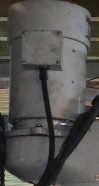
Older machines often used brushed DC spindle motors (these often have a fan on the side of them), while it may be possible to reuse the motor and drive, it is not recommended. The reason that these DC motors should not be used is because they use a phase angle Thyristor based controls and they can cause serious mains disturbance that may be outside of lawful limits. Many machines use 3 phase AC motors and most of these can be used again. You may want to consider getting the motor reconditioned.

Older machines often used brushed DC spindle motors (these often have a fan on the side of them), while it may be possible to reuse the motor and drive, it is not recommended. The reason that these DC motors should not be used is because they use a phase angle Thyristor based controls and they can cause serious mains disturbance that may be outside of lawful limits. Many machines use 3 phase AC motors and most of these can be used again.
(Click the relevant link above)
Using existing servo motors and drives"
Depending upon your experience fitting can be relatively simple but it is likely to take at least 40 hours of work. The major difficulty is normally connecting the drives, machines with "integrated" drives can be challenging, however some clients have found the task quite easy and quick. We do not want you to believe that the task is going to be simple it needs to be considered carefully.
A complete kit is normally quite straight forward to install, this is because the kit is supplied ready to fit and there are connectors for the motors, encoders etc. The more difficult items will be oilers, but this should not be to challenging. Items such as coolant pump, are ready to wire so should be quite easy to fit.
The best way to connect the coolant pump is via a three-phase solid state relay (SSR), this is included with every complete kit. Map software allows the user to choose any one of the 20 outputs, to drive your SSR. It is better to use a SSR than a conventional contactor, this is because when the contacts opens or closes they quite often cause an arc. The arc is caused by the collapsing magnetic field, this is called a back EMF and it can produce high voltages, these high voltages can damage electrics. Back EMFs can cause the controller to suffer disruptions or even damage. Using a SSR prevents this from happening.
If the encoders have a resolution of 1000 Pulses Per Revolution (PPR) or more they probably do not need to be changed. It is better to use encoders on the back of the motors rather then linear encoders, this is because linear encoders are subjected to any play in the ball screws. However, encoders have a marked effect on the precision of the machine and we recommend using encoders of at least 2000 PPR.
Milling machines and lathes are very difficult to protect from a safety point of view. If the machine is guarded, then you need to make sure that the guard switches work effectively. The MSD requires that there is an electomechanical break to ensure that the machine is safe when powered down. This is effected by using a 3 phase contactor and often a SSR. The idea is that the contactor never makes or breaks current, that is done by the SSR. It is very important to ensure that the operator is safe whenever manual intervention is needed!
Normally it is possible to use the existing controller arm. TRM are willing to make an adapter to allow the controller to be mounted of the original arm.
(Click the relevant link above)
Fitting your Kit
The PMC4 is provided with MAP sofware, Map allows the user to import G code. The most common G cades are supported as are many M codes commonly used in code generated via 2D CAD and 3D Cad.
There is a manual menu this can be used to set the origins and can also be used as a DRO screen, the user can also power up the machine and position all the axis manually using the keypad of the jog controller. By powering the machine down the machine can be used manually using the DROs but it is done against the resistance of the motors. On milling machines, the Z axis is unlikely to move manually.
There is a manual menu, this can be used to set the origins and can also be used as a DRO screen, and there is teach mode that allows the user to jog to position and then enter the learned position by pressing Enter on the key pad.
A USB can be used, the controller supports many but not all usb sticks and the files system FAT32.
Yes the controller can can store a large number of programs is the internal memories as long as the programs are 1000 lines or less.
The controller has a full PLC on board and when the controller encounters a Tool command (G Code T command) it will look for a program called "Tool" if it finds this it will preserve the screen and call the tool change program and run it.
(Click the relevant link above)
Programming and general questions
LVD 2014/35 EU Low Voltage Directive
The EU rolls out new rules to prevent unfair competition, as of April 20 2016 there is a new version of the Low Voltage Directive (LVD). This new law effects electrical equipment designed for use with a voltage rating of between 50 and 1000 V for alternating current and between 75 and 1500 V for direct current, other than the certain specified equipment. This directive is designed to enhance safety and prevent unfair competition in the market, so is likely to be good news for us that manufacture equipment in the EU and bad for companies that import cheap products from the far east. Please clip below to see some of the key points:Do I need a Risk Assessment?
The short answer is yes: “If you are an employer or self-employed. It is a legal requirement for every employer and self-employed person to make an assessment of the health and safety risks arising out of their work. The purpose of the assessment is to identify what needs to be done to control health and safety risks. Regulation 3 of the Management of Health and Safety at Work Regulations 1999.” (From the Health and Safety Executive Website - http://www.hse.gov.uk/risk/faq.htm#q8 ). Written by Businesswise Systems Ltd

Frequently asked questions
TRM Electronics aims to be a socially responsible organization that is involved in education and cancer research. The company has invented some new cancer treatments and aims to provide services and products that will benefit society and reduce energy consumption.